
Installing a Link standalone ECU is very exciting, and we want to make it as straight forward to you as possible.
- Each Link Plug-In ECU comes with an instruction manual to get you started. It is important to read through this manual start to finish before beginning installation.
- After reading the manual, the next step is to disconnect the battery, remove the factory ECU enclosure, and replace the factory circuit board with the anti-static strap on your wrist (ensuring any vehicle specific jumpers are set accordingly to your install requirements).
- Any additional sensors you wish to install need to be considered at this time, as well as considering the communications cable routing. The factory enclosure may need modification for additional wiring to be fed from the inside of the case to the outside.
- Download the PCLink software.
- Some factory sensors or inputs may be replaced with aftermarket sensors (e.g. narrowband oxygen sensor replaced with after market CAN-Lambda or wideband oxygen sensors) and could be wired to the factory ECU sensors, or wired to an expansion harness connection. Expansion harness can be ordered separately.
https://www.afrautoworksstore.com/products/link-xs-expansion-loom-xsl?_pos=1&_sid=6ea21fb4a&_ss=r
- An expansion harness allows you to utilise the additional inputs native to the ECU circuitry.
- Taking a picture like this can be good for referencing during wiring of additional sensors at a later date.
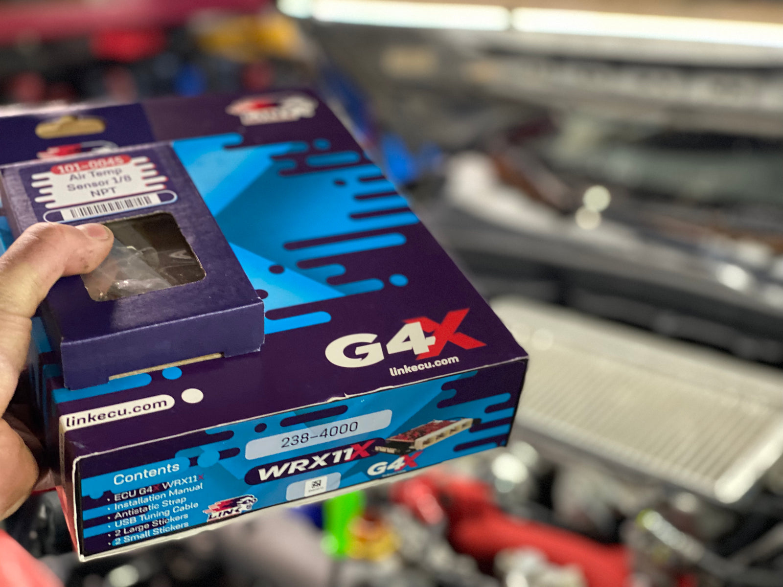
- The single most critical sensor is a fast acting intake air temp sensor. The ECU operates on “Speed Density” which requires accurate RPM, Manifold Pressure, and Charge Temperature to properly calculate the air mass entering the motor. https://www.afrautoworksstore.com/search?q=air+temp
- Some common sensors include
- Intake Air Temp – Includes options for some direct replacement fast acting IAT sensors like Nissan GTR
- CAN-Lambda or wideband oxygen sensor input
- Fuel Pressure for differential fuel pressure compensation
- Oil Pressure for logging and oil pressure safeties/oil pressure based rev limiters
- Flex Fuel Sensors
- Oil and Coolant Temp
- Switches/Dials for varying boost targets or map switching
- Shock travel
- Tire temp
- Wheel speed
- .. Sensor options are limitless.
- Physical installation of the IAT sensor can be performed with drilling and tapping or an appropriate weld in bung.
- Wiring of any engine sensor should always be done with proper tools, tug tested ensuring any crimps or connections are solid and permanent. Wiring should be protected from abrasion and heat.
- An “Unlock Code” is required to enable your ECU from your ECU dealer. Once connected to power the ECU can be unlocked by providing your dealer with the serial number.
- Configure all inputs and outputs to ensure they are operating as intended.
- All factory functions and additional sensors must be ensured operational.
- Pressing “R” brings up run time values, which is an easy way to cycle through all inputs and outputs.
- Set base timing with timing light, set base map in car appropriately for all parts.
- Car should now start up and run and base timing can be confirmed once car idles smoothly.
- Tune car on load bearing dyno. Enjoy!